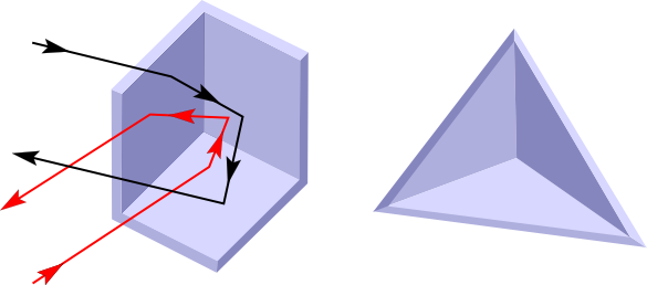

Light from the center of your eye bounces straight back to the center of your eye, so the image of your eye seems to be centered in the corner made by the mirrors.įor another way to use this Snack, tape five square mirrors together with the mirrored surfaces facing inward to form a box. If you pointed a thin beam of laser light right near the corner, the beam would bounce from mirror to mirror and then exit parallel to the entering beam. The inside corner of a corner reflector (where the three mirrors meet) sends light back parallel to its original path. Mirrors at other angles behave similarly, but the ray diagrams may get more complex. Light rays bounce off each mirror at the same angle that they hit the mirror: Physicists say that the angle of reflection is equal to the angle of incidence. The illustration below (click to enlarge) shows how an image is formed in the corner of two mirrors at 90 degrees. As you make the angle between the mirrors smaller, the light bounces back and forth more times, and you see more images. The number of images you see in the mirrors depends on the angle that the mirrors form. An image is formed each time the light bounces off a mirror. When you put an object between the two hinged mirrors, light from the object bounces back and forth between the mirrors before it reaches your eyes.

In a corner reflector, multiple reflections reverse the image and invert it. One eye may appear to be closer to the corner than the other. Move your head and notice that the pupil of your open eye always falls right at the corner. Now make a corner reflector by opening the two taped mirrors to 90 degrees and resting them on the third mirror, so that the three mirrors form a half cube (click to enlarge diagram).Ĭlose one eye and stare right at the corner where the three mirrors join. Notice that the right eye of this image is closed. Now close your right eye and look at two mirrors that form a 90-degree angle. Notice that the left eye of the image is closed. Remove the objects and see what happens when you draw different designs in the space between the two mirrors.Ĭlose your right eye and look at a single mirror straight on. Notice that the smaller the angle, the greater the number of images you see. You can use them both at the same time if you have separate radios or use them with a diplexer and a single run of coax with a dual band transceiver.To make a kaleidoscope, set the hinged mirrors on the cardboard and place an object such as a pencil or some coins between them. This means you can have two high gain, highly directional antennas in the same space of one VHF corner reflector. The Dual-Band Corner Reflector consists of two separate corner reflectors sharing the same boom structure. Gamma Match: Inline, Direct feed - UHF & N connector. Reflector Elements: 1/4" x 16" / 48" solid aluminum. Reflector Elements: 1/4" x 16" solid aluminum. Gamma Match: Inline, Direct feed - N connector. Reflector Elements: 1/4" x 32" solid aluminum. Gamma Match: Inline, Direct feed - UHF connector.

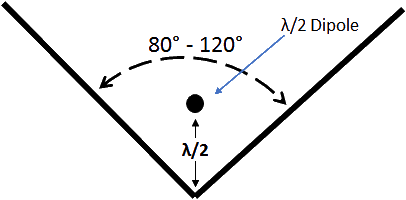
Reflector Elements: 1/4" x 48" solid aluminum. Regardless of your application, you'll be hard pressed to find a better way to spend your antenna dollar. The Corner Reflector has less phase distortion causing less errors and fewer re-tries. The Corner Reflector is reported to give better performance for packet and high speed data links than long boom yagis even though the yagi had a higher S reading than the Corner Reflector. The Corner Reflector gives you the gain of a 10+ foot Yagi with almost double the front to back ratio and a much wider bandwidth. The screen was then formed into a right angle to improve the forward gain and front-to-back ratio which created the corner reflector. The single reflector was turned into a screen for a greater back and side rejection. In the logical progression of antennas, the ordinary dipole gave way to the Yagi-Uda which utilized directors and a reflector.


 0 kommentar(er)
